Choosing the right preformed armor rods for ACSR conductors comes down to one critical parameter: the conductor's outer diameter. The armor rod model must precisely match the conductor diameter to ensure proper gripping force, effective stress distribution, and long-term performance. In this guide, we walk through the complete selection process for Vilun AR Series armor rods, covering key parameters, common selection mistakes, and differences between ACSR, AAC, and AAAC conductors. Whether you are specifying armor rods for a new transmission line or replacing damaged conductor protection fittings, this guide will help you make the correct choice.
When selecting helical armor rods (also called preformed line protection rods), four parameters determine the correct model:
Conductor outer diameter (mm): The most important parameter. Armor rods are designed to grip a specific conductor diameter. An incorrect match results in either loose fitting (insufficient grip) or over-compression (conductor deformation).
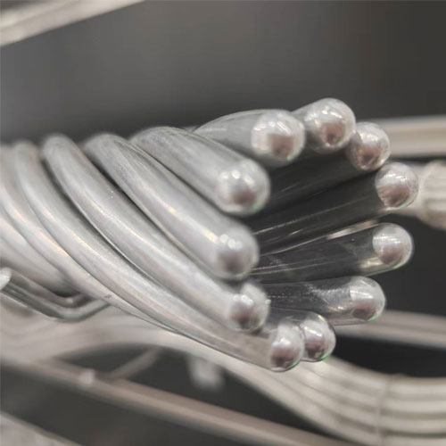
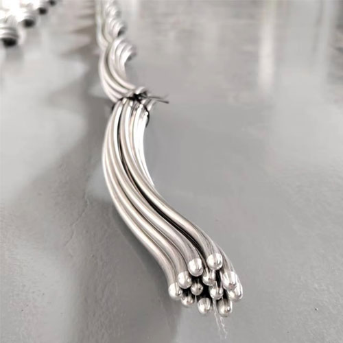
Rod diameter (mm): The individual rod thickness, which affects the mechanical strength and stress distribution capability of the rod set.
Rod length (mm): Determines the protection coverage area along the conductor. Longer rods distribute stress over a greater length, reducing peak stress concentration.
Rods per set: The number of individual rods that wrap around the conductor. More rods provide better stress distribution and higher gripping force.
Vilun's AR Series covers conductor cross-sections from 50 mm² to 800 mm². Use the table below to match your conductor to the correct armor rod model:
Catalog Number Single/Double support
| Diameter Range (mm)
| Conductor Type (GB-1179-83) ACSR LGJ/LGJF | Length (mm)
| Weight (kg)
| Color Code
|
AR-0114 AR-0314 | 7.85-8.28 | | 1110 1420 | 0.3 0.4 | Red |
AR-0117 AR-0317 | 9.31-9.88 | 50/8 | 1270 1580 | 0.4 0.5 | Black |
AR-0120 AR-0320 | 11.10-11.76 | 50/30,70/10 | 1370 1680 | 0.6 0.7 | Blue |
AR-0123 AR-0323 | 13.24-14.00 | 70/40,95/15,90/20 | 1470 1780 | 0.7 0.8 | Black |
AR-0124 AR-0324 | 14.01-14.86 | 120/7 | 1520 1830 | 0.8 1.0 | Red |
AR-0125 AR-0325 | 14.87-15.39 | 120/20 | 1580 1880 | 0.9 1.1 | Black |
AR-0126 AR-0326 | 15.40-16.00 | 95/55,120/25,150/8 | 1630 1930 | 1.0 1.1 | Purple |
AR-0128 AR-0328 | 16.65-17.25 | 150/20,150/25 | 1680 1980 | 1.1 1.3 | Brown |
AR-0129 AR-0329 | 17.26-17.86 | 150/35 | 1730 2030 | 1.3 1.5 | Blue |
AR-0130 AR-0342 | 17.87-18.80 | 120/70,185/10 | 1830 2130 | 1.4 1.6 | Green |
AR-0131 AR-0132 | 18.81-19.86 19.87-20.68 | 185/25,185/30,185/40,210/10 210/25,210/35 | 1830 1930 | 1.5 2.0 | Orange Purple |
AR-0133 | 20.69-21.46 | 210/50 | 1930 | 2.0 | Red |
AR-0134 | 21.47-23.04 | 240/30,240/40,240/55,300/15 | 1980 | 2.2 | Blue |
AR-0135 | 23.05-23.60 | 300/20 | 2030 | 2.5 | Green |
AR-0136 | 23.61-24.79 | 300/25,300/40,300/50 | 2230 | 2.7 | White |
AR-0137 | 24.80-25.81 | 300/70 | 2340 | 2.5 | Yellow |
AR-0138 | 25.82-26.29 | 400/25 | 2380 | 4.2 | Brown |
AR-0139 | 26.30-27.03 | 400/20,400/35 | 2430 | 4.2 | Blue |
AR-0140 | 27.04-27.89 | 400/50 | 2430 | 4.2 | Green |
AR-0141 | 27.90-28.93 | 400/65 | 2540 | 4.7 | Orange |
AR-0142 | 28.94-29.49 | 400/95 | 2540 | 4.8 | Purple |
AR-0143 | 29.50-30.68 | 500/35,500/45 | 2540 | 5.2 | Red |
AR-0144 | 30.69-32.23 | 500/65 | 2540 | 5.85 | Black |
AR-0145 | 32.24-33.71 | 630/45 | 2540 | 5.9 | White |
AR-0146 | 33.72-35.31 | 630/55 | 2540 | 6.2 | Yellow |
Identify your conductor type and specification. Determine whether you are using ACSR (LGJ), AAC, or AAAC, and note the cross-section and stranding configuration (e.g., LGJ-240/30 means 240 mm² aluminum with 30 mm² steel core).
Look up the conductor outer diameter. This is the physical outside diameter of the completed conductor, not the cross-sectional area. Refer to the conductor manufacturer's datasheet or standard tables.
Match the diameter to a AR Series model. Using the table above, find the model whose conductor diameter matches yours. The match must be exact—do not approximate.
Verify the rod parameters. Confirm that the rod diameter, length, and number of rods per set are appropriate for your application. For suspension points with higher mechanical loads, longer rods with more rods per set provide enhanced protection.
Consider environmental and voltage factors. For coastal or industrial areas, the aluminum alloy material provides inherent corrosion resistance. For high-voltage lines up to 345 kV, specify corona-resistant armor rods.
Armor rod selection depends partly on the conductor type. Here is a brief comparison:
| Property | ACSR (LGJ) | AAC | AAAC |
|---|
| Material | Aluminum + Steel core | All Aluminum | All Aluminum Alloy |
| Strength | High (steel reinforcement) | Medium | High |
| Corrosion resistance | Moderate (steel core may corrode) | Excellent | Excellent |
| Common use | Long-span transmission | Distribution, coastal | Transmission, distribution |
Vilun AR Series armor rods are compatible with all three conductor types. The key is matching the outer diameter—regardless of internal construction, the armor rod grips the outer surface. For ACSR conductors, armor rods also provide an additional benefit: they protect the aluminum strands from fatigue at suspension clamps, where the steel core creates a stiffness transition point.
Mistake 1: Selecting by cross-section area alone. Two conductors with the same cross-section (e.g., 240 mm²) may have different outer diameters depending on stranding ratio. Always verify the actual outer diameter.
Mistake 2: Using a "close enough" model. An armor rod designed for 21.60 mm will not properly grip a 23.01 mm conductor. Even a 1 mm mismatch can compromise performance.
Mistake 3: Ignoring rod count. Models with fewer rods per set distribute stress less evenly. For critical applications, prefer models with higher rod counts where available.
Mistake 4: Overlooking repair application requirements. When using armor rods for conductor repair (damaged outer strands), ensure the rod length covers the full damaged area plus adequate overlap on each side.
One of the most common challenges in armor rod selection is finding the correct conductor outer diameter. The table below lists common ACSR conductor types and their outer diameters to help you cross-reference with the VAR Series:
| Conductor Designation | Aluminum (mm²) | Steel Core (mm²) | Outer Dia. (mm) | Recommended VAR Model |
|---|
| LGJ-95/15 | 95 | 15 | 13.61 | AR-95/15 |
| LGJ-120/7 | 120 | 7 | 14.50 | AR-120/7 |
| LGJ-150/8 | 150 | 8 | 16.00 | AR-150/8 |
| LGJ-185/10 | 185 | 10 | 18.00 | AR-185/10 |
| LGJ-240/30 | 240 | 30 | 21.60 | AR-240/30 |
| LGJ-300/15 | 300 | 15 | 23.01 | AR-300/15 |
| LGJ-400/20 | 400 | 20 | 26.91 | AR-400/20 |
| LGJ-800/100 | 800 | 100 | 38.40 | AR-800/100 |
Important: The table above covers standard ACSR (LGJ) conductors per Chinese national standards. If you are using AAC or AAAC conductors, or conductors manufactured to other international standards (e.g., ASTM, BS, DIN), you must verify the actual outer diameter from the conductor manufacturer's datasheet. Conductor designations vary between standards—a "Drake" ACSR conductor per ASTM has a different designation but may have a similar diameter to an LGJ conductor. Always select armor rods based on the physical outer diameter, not the name designation.
Different installation scenarios may require specific attention beyond basic model selection:
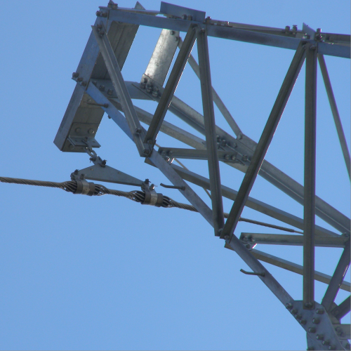
Suspension point protection: This is the most common application. Armor rods are installed at each suspension clamp to distribute the bending stress and clamping pressure. The rod set length should extend well beyond the clamp edges on both sides to ensure progressive stress transfer. For standard applications, the AR Series rod lengths (1,400–2,500 mm) provide ample coverage.
Tension point protection: At tension (dead-end) points, the conductor experiences different stress patterns than at suspension points. Armor rods at tension points help distribute the stress concentration at the tension clamp grips. In some designs, armor rods are used in combination with other fittings for enhanced protection.
Repair of damaged conductors: When conductor outer strands are damaged by fatigue, arcing, or mechanical impact, armor rods can restore mechanical and electrical integrity. For repair applications, select a model whose rod length exceeds the damaged area length by at least 300 mm on each side to ensure adequate overlap onto undamaged conductor.
High-voltage applications: For transmission lines operating at voltages up to 345 kV, standard armor rods may not provide adequate corona performance. Vilun offers corona-resistant armor rod variants with optimized helical pitch and surface treatment to minimize corona discharge and radio interference under high electrical stress.
Severe environment applications: In coastal areas with salt spray, industrial zones with chemical pollution, or tropical regions with high humidity, the aluminum alloy material of VAR Series armor rods provides inherent corrosion resistance. No additional protective coating is required under normal service conditions within the −40 °C to +80 °C operating temperature range.
Vilun AR Series armor rods are manufactured to GB/T 2314 (general technical requirements for electric power fittings), DL/T 763-2001 (technical specification for preformed armor rods), and relevant IEC standards. Vilun is ISO 9001 certified, ensuring consistent quality across its 20,000-set-per-month production capacity. The aluminum alloy material achieves ≥ 95% IACS conductivity and ≥ 160 MPa tensile strength, with an operating temperature range of −40 °C to +80 °C.
If you are unsure which AR Series model fits your conductor, contact Vilun's technical team through
vilunfittings.com. Provide your conductor type (ACSR/AAC/AAAC), cross-section, and outer diameter, and Vilun's engineers will recommend the correct model. Custom solutions are available for non-standard conductor sizes.